Hi, this is Jon Cross with Ohio Lumex. I will cover some of the basic elements of our ammonia sorbent traps. First, I’ll lay out several of the key advantages sorbent traps have over other methods in general; then, I’ll give a summary of the sampling procedure, the reasons for measuring ammonia, and briefly touch on method performance.
This is meant to serve as an introduction to ammonia sorbent traps, not as a comprehensive user’s guide. If you plan to use ammonia sorbent traps, I suggest you contact us to go over the details of your application and ensure you will be successful. Before discussing ammonia traps specifically, let’s go over some of the core concepts of sorbent traps.

The concepts I’ll describe cover all of the Ohio Lumex sorbent trap methods modeled after EPA Method 30B. This includes sorbent traps for mercury, ammonia, SO3, hydrogen halides (HCl), Selenium, and Arsenic.
These sorbent trap methods are designed to be sampled directly in the sample gas and sampled simultaneously in co-located pairs. The standard sorbent trap contains two sections of sorbent material (Figure 1). The first section, labeled S1 in the diagram on below, serves as the primary capture section and is where we expect all of the target analyte to be collected. Our laboratory can also spike this first section with a known mass of the target analyte to allow for a field spike recovery run, which I will explain shortly.
Figure 1:
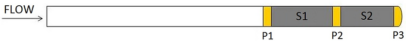
Section two is always made of the same sorbent material as section one. Section two is the breakthrough section and serves as a means to determine whether the target analyte has broken through section one during sampling.
Every type of sorbent trap has its own unique set of sampling parameters, including temperature, flow, acceptable vacuum, and sampling duration. We will go over specific sampling parameters shortly.
Each sorbent trap is hand-made and can be customized in a variety of ways to meet the needs of a specific application.
The robustness of Method 30B and all methods designed to emulate it is rooted in the built-in QA/QC. That is to say; the method includes several self-validating performance criteria. This includes pair agreement, breakthrough, and spike recovery. Good pair agreement simply means two sorbent traps sampled simultaneously in the same location produce nearly the same measurement, within a defined range of acceptability.
Similarly, a good breakthrough measurement is one where on any individual trap, the ratio of analyte mass collected on section two versus the analyte mass collected on section one is very low, or below a defined threshold.
Finally, spike recovery is a measurement of how much pre-spiked mass is recovered from section one of a sorbent trap. It is used to verify the performance of the combined sampling and analysis of the test method, as defined in Section 13 of Method 30B. According to the method, spiked traps should be sampled alongside an unspiked trap to perform the spike recovery calculation.
Let’s give a quick example to clarify how this works. Say you’re sampling two traps, we’ll call them Traps A and B. Trap A has been spiked by our laboratory with 50ug of the target analyte, while Trap B has not been spiked. You sample the same gas volume through both traps, send them to our lab, and we do the analysis. We find that Trap A has 90ug, while trap B has 40ug. This is a perfect spike recovery because the difference between the traps equals the spike mass, 50ug.
Ohio Lumex has focused on developing sorbent trap methods because they provide several advantages over older methods, particularly methods that require the use of impinger trains, such as Methods 26, 29, 8A, and CTM 027.
Sorbent trap sampling equipment is much more portable than these impinger-based methods since the required equipment is much more compact. A complete trap sampling system can be assembled within a couple of minutes, and a sampling technician can move the entire system from one location to another in a single trip.
The sampling procedure is much simpler than older methods, mostly due to the convenience of sampling through a dry material in-situ rather than extracting the analyte into a condenser coil or series of impingers, which must then be rinsed and prepared for the next run. Performance-based QA/QC criteria, particularly pair agreement and field spike recovery, provide a substantial advantage over impinger-based methods.
Using sorbent traps, the sampling technician does not need to deal with the hassle of using acids or other liquid reagents on-site. Sorbent traps were designed for use in nearly all sampling environments, including those upstream of particulate control devices. This sets the traps apart from impinger-based methods, which often fail in these environments.
Moving on to ammonia, the ammonia trap was developed to provide an alternative to CTM 027 and EPA Method 320, which use impingers and FTIR, respectively. These traps have primarily found use at coal-fired and natural gas power plants, with most sampling taking place at the outlet of SCR systems.
The primary applications for ammonia sorbent traps include:
- Measuring ammonia slip
- Determining the effect of ammonia concentration on Hg oxidation
- Optimizing SCRs in conjunction with the development of catalyst management plans
In the graph below, you’ll see a correlation between measured DeNOx percentages across an SCR and predicted ammonia slip. The graph’s point is to highlight the fact that many power plants use a model to determine ammonia concentrations rather than using real measurements. These models can use NOx concentrations going into and out of the SCR, as well as other inputs such as the expected reaction potential of the catalyst based on its age. However, real measurements are better than models.
Effect of DeNOx Target on Ammonia Slip:
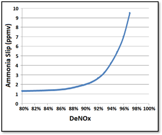
In our experience, ammonia slip models often fail to reflect reality, and in some cases, real ammonia concentrations have exceeded expected concentrations by a factor of 20. Ammonia slip can create problems for downstream monitoring equipment, exacerbate ammonium bisulfate formation, especially at lower temperatures, and create fly ash disposal issues if significant ammonia adsorbs to it.
Excess ammonia concentrations can also suppress mercury oxidation across the SCR. Oxidation of mercury is critical to keep stack emissions low. When the gas makes it to the FGD, most oxidized mercury will be absorbed, but the elemental mercury will go straight through and out the stack. In this way, ammonia at the SCR and mercury in the stack are inextricably linked.
The bar graph below shows how mercury oxidation is related to ammonia concentrations using deNOx measurements as a somewhat inaccurate, but still positively correlated proxy. These data come from a 3-layer catalyst. Mercury measurements were taken at the inlet to the SCR, after the second catalyst layer, and at the SCR outlet.
Suppression of Hg Oxidation by Ammonia:
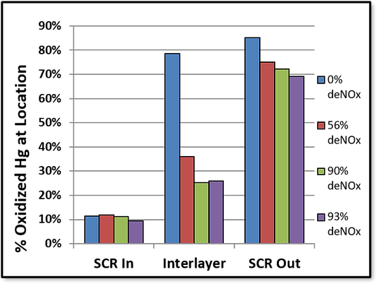
The graph’s four colors represent different DeNOx percentages, including 0, 56, 90, and 93. As expected, higher DeNOx results in lower mercury oxidation. Additionally, we can see that most mercury oxidation occurs on the last layer of the catalyst if you look at the difference between the interlayer and SCR outlet mercury oxidation percentages. The point again is to illustrate how ammonia and mercury are linked, and how direct ammonia measurements are a useful tool in diagnosing problems with the catalyst and optimizing its performance.
The distribution and reaction of injected ammonia through an SCR is critical to how the SCR performs. SCR optimization and development of a robust catalyst management plan should include, at a minimum, accurate measurements of ammonia and an understanding of how it interacts with other gas constituents.
When it comes to sampling equipment used to sample sorbent traps, the Ohio Lumex OLM30B Sorbent Trap Sampling System has three core components, including a stainless-steel probe, desiccant canisters, and a sampling console.
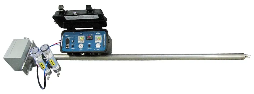
The probe includes two trap liners for traps with a 10mm outer diameter, a cooling air inlet, a stack thermocouple, and a 750W heater. The cooling air inlet is very important for most applications, as I’ll explain shortly.
Sorbent Trap Sampling Diagram using the OLM30B:
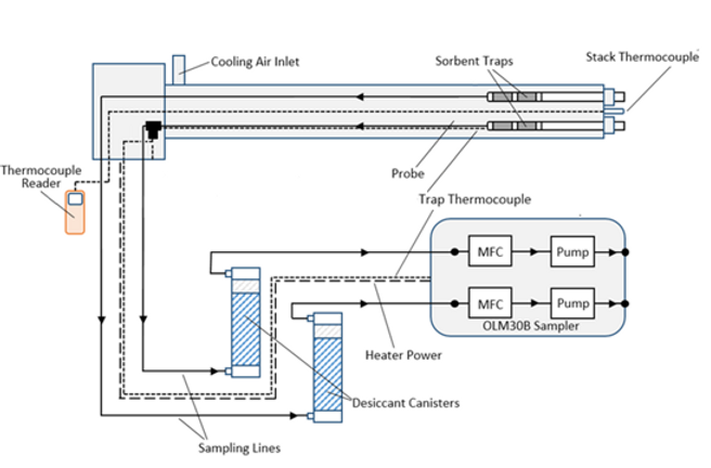
The desiccant canisters remove water and acid gases from the sample gas stream to protect the console, while the sampling console itself features two mass flow controllers and two pumps. For most sampling scenarios, sorbent trap runs will take about 30 minutes. However, I recommend you contact Ohio Lumex to determine your application’s ideal flow rate and sample duration.
When sampling ammonia sorbent traps, it is critical to maintain trap temperature within a narrow range between 100 and 120°C. Failure to stay below 120°C may result in breakthrough.
As discussed earlier, these traps are often used at the outlet of an SCR, which is generally around 280-350°C at a coal-fired power plant.
To get the trap temperature down into a nominal range, compressed plant air needs to be supplied to the probe’s cooling air inlet. The problem is, pushing cold air through a probe that is continuously being heated by duct gas creates a situation where the probe is not at a uniform temperature. Therefore, a standard built-in trap thermocouple is not likely going to measure the sorbent’s real temperature, even if it’s only a few inches away from the trap. Additionally, it can be challenging to find the right amount of cooling air to ensure a stable probe temperature while sampling.
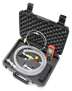
To solve these problems, Ohio Lumex has developed a fine temperature control kit for sorbent trap sampling. The kit includes an in-line thermocouple that rests inside the trap liner and measures temperature just a few millimeters behind the sorbent trap. It also contains an air-flow control system to adapt from plant air to the probe and allow for fine control of cooling air.
If sampling downstream of an air preheater, it shouldn’t be necessary to use plant air. In that case, a portable blower is usually sufficient to provide enough cooling air.
Particulate matter in the gas stream is another factor that needs to be considered when sampling ammonia sorbent traps. It is important to prevent particulate matter from getting into the sorbent trap, as it may result in a high bias. These sorbent traps are designed only to measure vapor-phase ammonia. The measurements must exclude any ammonium salt aerosols that may reside in the gas stream or ammonia that has adsorbed onto fly ash. However, it is important to mention here that ammonium salt aerosols WILL form inside the trap on the glass’s surface due to the low trap temperature. Condensed ammonium salts will be analyzed along with the rest of the trap, and the ammonia mass is included in the total measurement since it was originally vapor-phase ammonia before it condensed in the trap.
For nearly all sampling scenarios, static pre-filters are perfectly suitable for preventing particulate matter from entering the sorbent trap. This filter is an inert material situated at the front end of the sorbent trap, meaning it rests inside the gas stream and is always at the same temperature as the gas. High-velocity duct gas flows across the face of the filter rather than through it, resulting in very little accumulation of particulate matter.
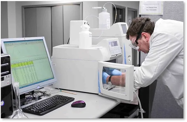
I won’t go into great detail on how the sorbent traps are analyzed, but I’ll highlight a few key elements that are important for anyone interested in using ammonia sorbent traps:
- When you send your ammonia traps to our lab, we will rinse out the condensate, dissolve the sorbent, and analyze the traps for total ammonium content by ion chromatography. Sorbent traps are analyzed in large batches, and since the method is not destructive, it is possible to re-analyze sample solutions if necessary.
- The analytical method uncertainty has been measured to be approximately 5%, and all method performance criteria draw direct parallels with Method 30B. To expand further, all calibrations and calibration verifications must meet specified performance criteria within 10% for the results to be reported as valid.
Let’s recap some of the essential points we’ve discussed:
- The ammonia sorbent trap method provides an alternative to the impinger-based CTM 027 and FTIR. Sorbent traps are cost-effective, easy to use and provide excellent data quality.
- Real ammonia slip data is superior to predicted concentrations based on DeNOx models, and it is important to get actual measurements of ammonia to understand SCR efficiency. Excess ammonia can lead to ammonia slip, which can cause downstream monitoring equipment to fail, produce ammonium bisulfate in the SCR and air preheater, and suppress mercury oxidation at the last layer of the SCR.
- Finally, the ammonia sorbent trap is a trusted method of measuring ammonia because it is modeled after Method 30B, the reference method for Hg. The sorbent trap method includes built-in QA/QC to ensure high-quality measurements, including pair agreement, breakthrough, and spike recovery.
If you have any additional questions about ammonia sorbent traps or anything related to your monitoring needs, please contact us, and we’ll be happy to assist!