Hi, this is Jon Cross with Ohio Lumex. We’ll be covering some of the features and applications for SO3 sorbent traps, several of the key advantages sorbent traps have over other methods in general, and finally, a summary of the SO3 trap sampling procedure, some example data from SO3 measurement projects, and a few things to keep in mind when choosing how and where to sample.
This is meant to serve as an introduction to SO3 sorbent traps, not as a comprehensive user’s guide. If you plan to use SO3 sorbent traps, I suggest you contact us so we can go over the details of your application to ensure your success. Before discussing SO3 traps specifically, let’s go over some of the core concepts of sorbent traps.

These sorbent trap methods are designed to be sampled directly in the sample gas and sampled simultaneously in co-located pairs. The standard sorbent trap contains two sections of sorbent material (Figure 1). The first section, labeled S1 in the diagram on below, serves as the primary capture section and is where we expect all of the target analyte to be collected. Our laboratory can also spike this first section with a known mass of the target analyte to allow for a field spike recovery run, which I will explain shortly.
Figure 1:
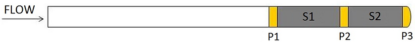
Section two is always made of the same sorbent material as section one. Section two is the breakthrough section and serves as a means to determine whether the target analyte has broken through section one during sampling.
Every type of sorbent trap has its own unique set of sampling parameters, including temperature, flow, acceptable vacuum, and sampling duration. We will go over specific sampling parameters shortly.
Each sorbent trap is hand-made and can be customized in a variety of ways to meet the needs of a specific application.
The robustness of Method 30B and all methods designed to emulate it is rooted in the built-in QA/QC. That is to say; the method includes several self-validating performance criteria. This includes pair agreement, breakthrough, and spike recovery. Good pair agreement simply means two sorbent traps sampled simultaneously in the same location produce nearly the same measurement, within a defined range of acceptability.
Similarly, a good breakthrough measurement is one where on any individual trap, the ratio of analyte mass collected on section two versus the analyte mass collected on section one is very low, or below a defined threshold.
Finally, spike recovery is a measurement of how much pre-spiked mass is recovered from section one of a sorbent trap. It is used to verify the performance of the combined sampling and analysis of the test method, as defined in Section 13 of Method 30B. According to the method, spiked traps should be sampled alongside an unspiked trap to perform the spike recovery calculation.
Let’s give a quick example to clarify how this works. Say you’re sampling two traps, we’ll call them Traps A and B. Trap A has been spiked by our laboratory with 50ug of the target analyte, while Trap B has not been spiked. You sample the same gas volume through both traps, send them to our lab, and we do the analysis. We find that Trap A has 90ug, while trap B has 40ug. This is a perfect spike recovery because the difference between the traps equals the spike mass, 50ug.
Ohio Lumex has focused on developing sorbent trap methods because they provide several advantages over older methods, particularly methods that require the use of impinger trains, such as Methods 26, 29, 8A, and CTM 027.
Sorbent trap sampling equipment is much more portable than these impinger-based methods since the required equipment is much more compact. A complete trap sampling system can be assembled within a couple of minutes, and a sampling technician can move the entire system from one location to another in a single trip.
The sampling procedure is much simpler than older methods, mostly due to the convenience of sampling through a dry material in-situ rather than extracting the analyte into a condenser coil or series of impingers, which must then be rinsed and prepared for the next run. Performance-based QA/QC criteria, particularly pair agreement and field spike recovery, provide a substantial advantage over impinger-based methods.
Using sorbent traps, the sampling technician does not need to deal with the hassle of using acids or other liquid reagents on-site. Sorbent traps were designed for use in nearly all sampling environments, including those upstream of particulate control devices. This sets the traps apart from impinger-based methods, which often fail in these environments.
Moving onto SO3, the SO3 trap was developed to provide an alternative to the controlled condensate method known as CTM-13 or Method 8A. This method was designed for Kraft recovery furnaces, not for sampling near SCRs at coal-fired power plants. Although there are some ways to modify the controlled condensate method for sampling gas with a high concentration of particulate matter, controlled condensate still struggles to perform well in these environments.
In 2019, several utilities funded a project with the Electric Power Research Institute to compare the sorbent trap method with controlled condensate in a controlled laboratory setting. The study found that the sorbent trap method provides accurate measurement of flue gas SO3 concentrations, while the controlled condensate method is subject to loss of analyte on various sample surfaces upstream of the condenser coil, as well as breakthrough of the condenser coil itself.
For the sorbent trap method to be used as a compliance method, it has to go through a Method 301 validation. Ohio Lumex is currently working on this to allow our customers to use sorbent traps for compliance with emission limits.
The primary applications for SO3 sorbent traps include the evaluation of acid gas control, such as dry sorbent injection… measuring SO2 oxidation across an SCR, measurement of sulfuric acid in stacks, and determining the impact of SO3 on powdered activated carbon used for Hg capture.
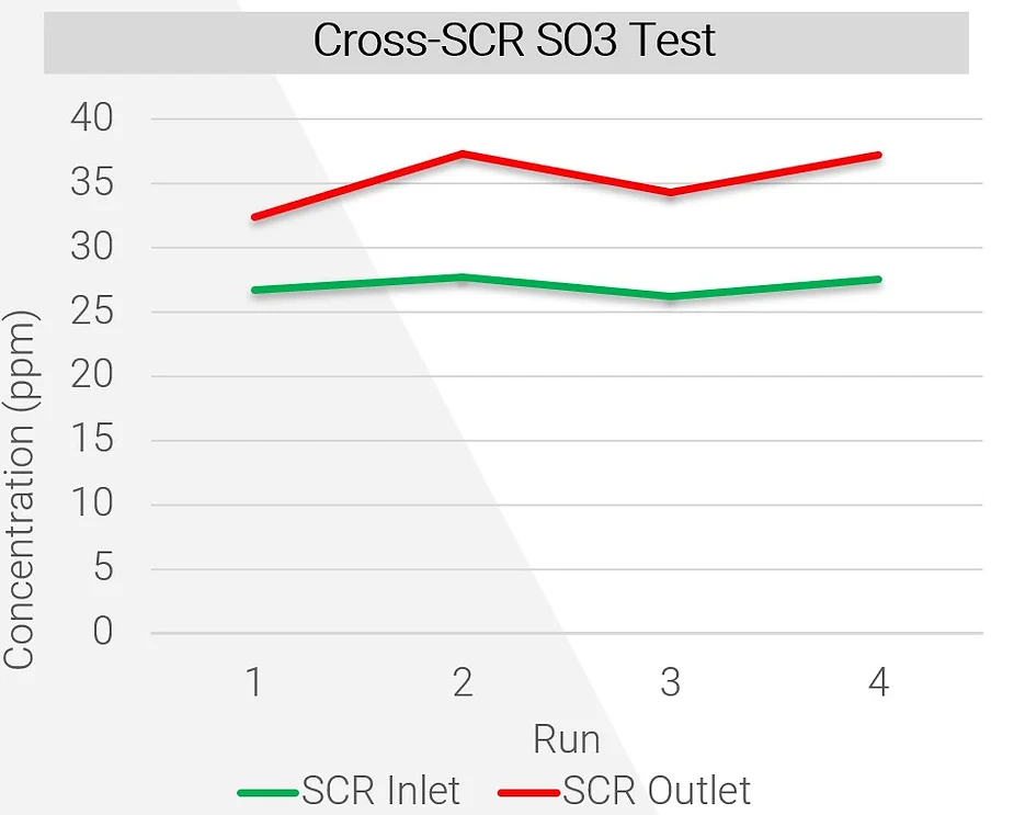
The most common application for SO3 sorbent traps is to measure SO3 before and after an SCR. The SCR will naturally convert some SO2 to SO3. If concentrations are high enough and gas temperatures low enough, the SO3 and sulfuric acid will combine with ammonia to form ammonium bisulfate (or ABS). ABS sticks to the surfaces of catalysts, reducing its overall surface area and efficiency. It also condenses inside air preheaters, causing corrosion and pluggage. Many coal-fired units around the country have been required to run at a very low load for extended periods, which exacerbates ABS formation due to the reduced operating temperature. The ABS formation temperature is a function of several variables, including ammonia and SO3 concentrations. Essentially, if SO3 concentrations can be reduced, it is possible to run a coal-fired unit at a lower minimum operating temperature without creating problems for the SCR and air preheater. One of the ways to reduce SO3 concentration is to use dry sorbent injection (or DSI). A typical engineering study using SO3 sorbent traps involves sampling at the inlet and outlet of an SCR while injecting DSI upstream of the SCR, then varying the DSI injection rate to determine how much SO3 is removed at each rate. This sort of test allows plant operators to know how much DSI is required to reduce ABS formation temperature to an acceptable level, thereby enabling the plant to run at a reduced load.
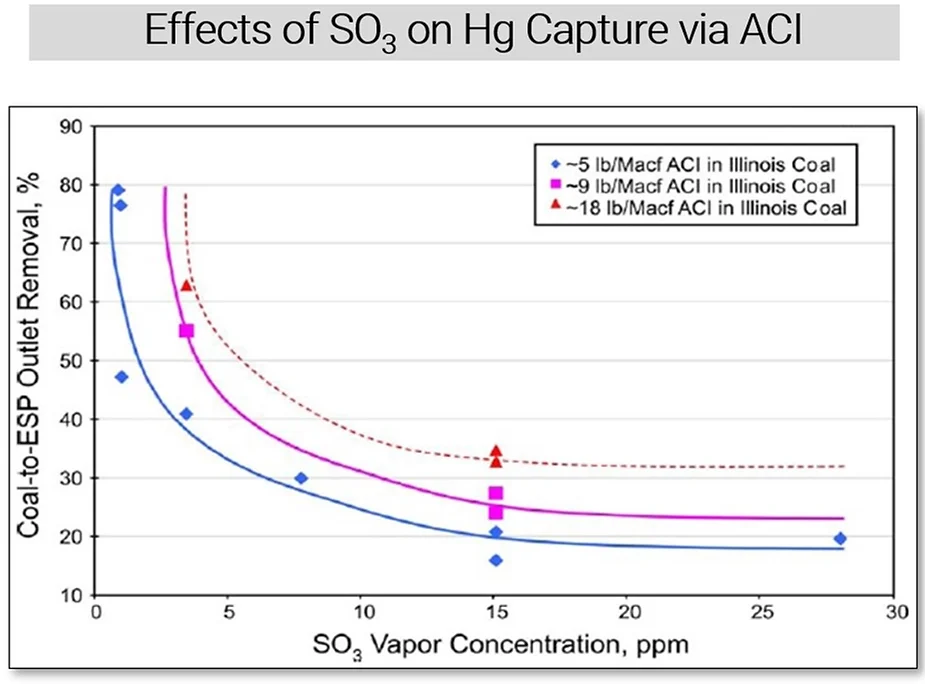
The graph below shows several correlation curves between SO3 concentration and percent-removal of Hg by using three different rates of activated carbon injection (or ACI). The effect of SO3 on Hg mitigation is clear – at higher SO3 concentrations, ACI is less effective at capturing mercury. SO3 competes with Hg for active sites on the carbon, and at sufficiently high enough concentrations, it can render the carbon barely effective at all. This is another application where SO3 sorbent traps can be used, in conjunction with mercury sorbent traps. It is especially useful at facilities where both DSI and ACI are employed, and operators want to minimize material costs by optimizing injection rates. In many cases, better Hg capture can be achieved not by increasing ACI, but by increasing DSI to reduce SO3, thereby increasing the ACI’s effectiveness without changing the amount of carbon being used.
Another common application for SO3 sorbent traps is to measure sulfuric acid emissions at a power plant stack. There are also continuous emissions monitors for this application, but a monitor may not be a cost-effective solution for short-term testing.
The dataset provided below is an example of a short-term measurement project to determine sulfuric acid emissions at a stack with six sorbent trap pairs sampled in one day.
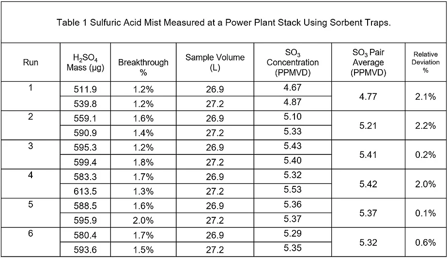
Sulfuric acid mist contributes to opacity, and at sufficiently high concentrations, can result in blue plume. A few SO3 sorbent trap stack measurements can help plant operators know how much sulfuric acid is contributing to opacity and how close they are to having a compliance problem.
Note, due to the lower temperatures compared to SCR locations, sampling in the stack requires isokinetic sampling equipment.
When it comes to sampling equipment used to sample sorbent traps, the Ohio Lumex OLM30B Sorbent Trap Sampling System has three core components, including a stainless-steel probe, desiccant canisters, and a sampling console.
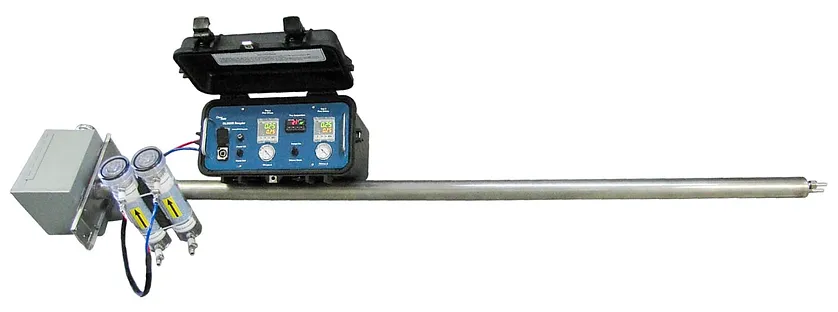
The probe includes two trap liners for traps with a 10mm outer diameter, a cooling air inlet, a stack thermocouple, and a 750W heater. The cooling air inlet is very important for most applications, as I’ll explain shortly.
Sorbent Trap Sampling Diagram using the OLM30B:
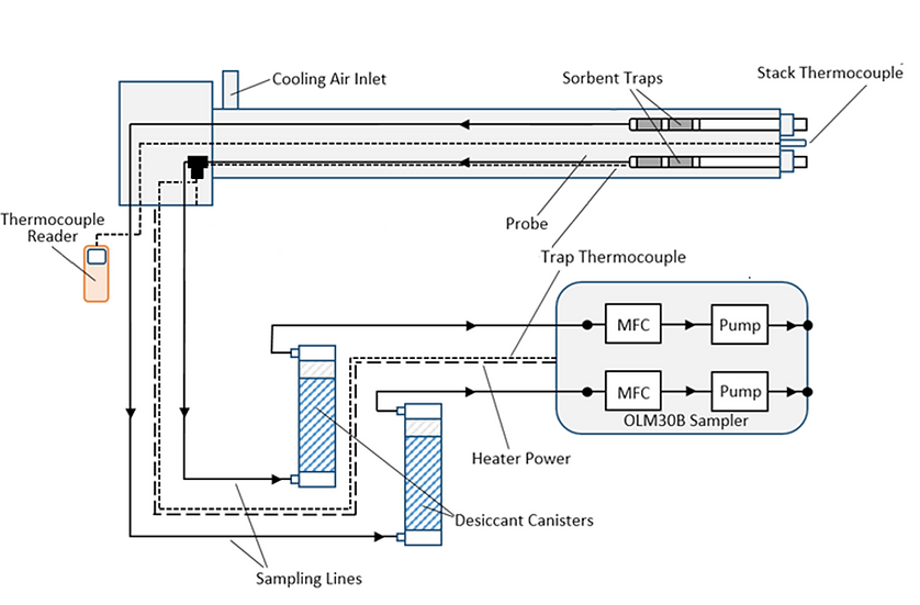
The desiccant canisters remove water and acid gases from the sample gas stream to protect the console, while the sampling console itself features two mass flow controllers and two pumps. For most sampling scenarios, sorbent trap runs will take about 30 minutes. However, I recommend you contact Ohio Lumex to determine your application’s ideal flow rate and sample duration.
When sampling SO3 sorbent traps, it is critical to maintain trap temperature within a narrow range between 200 and 230°C. Sampling outside this range may result in either low bias or breakthrough.
As discussed earlier, these traps are often used at the inlet and outlet SCRs, which at a coal-fired power plant, is generally around 280-350°C.
To get the trap temperature down into a nominal range, compressed plant air needs to be supplied to the probe’s cooling air inlet. The problem is, pushing cold air through a probe that is continuously being heated by duct gas creates a situation where the probe is not at a uniform temperature. Therefore, a standard built-in trap thermocouple is not likely going to measure the sorbent’s real temperature, even if it’s only a few inches away from the trap. Additionally, it can be challenging to find the right amount of cooling air to ensure a stable probe temperature while sampling.
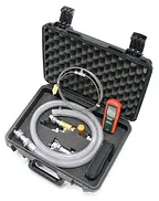
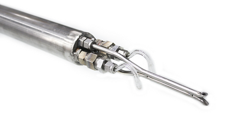
To solve these problems, Ohio Lumex has developed a fine temperature control kit for sorbent trap sampling. The kit includes an in-line thermocouple that rests inside the trap liner and measures temperature just a few millimeters behind the sorbent trap. It also contains an air-flow control system to adapt from plant air to the probe and allow for fine control of cooling air.
When sampling upstream of a particulate control device, as is often the case when sampling near SCRs, it is necessary to filter the sample gas entering the trap. Particulate matter may contain sulfate compounds that will bias the results or completely plug a trap and prevent sampling. When there is a need to filter sample gas, Ohio Lumex generally prescribes one of two filtration methods.
Static pre-filters are the default filtration method and will work for the majority of sampling environments. They are essentially a plug of inert material placed into the trap and sit flush with the trap’s tip. Since the duct gas moves at a high velocity across the filter’s surface, there’s little opportunity for particulate matter to accumulate. These filters are put into traps during the production process, so there’s no additional work for the sampling technician to do in the field. The sampling procedure is the same as it is without static pre-filters, making this the easiest filtration method to use.
For locations with extremely high particulate matter, especially immediately downstream of a DSI probe location, inertial filtration may be required. Inertial filtration relies on the inertia of high-velocity particulate matter to separate particulate from gas. Essentially, each sorbent trap is fitted with a custom-made inertial filter and eductor. The eductor uses compressed plant air to pull sample gas across the filter’s surface at an extremely high velocity. Simultaneously, the sampler pumps pull gas through the filter and into the trap. The suction created by the pumps is not powerful enough to overcome the inertia of the particulate, so it escapes the filter and goes back into the duct.
Some applications, such as measuring sulfuric acid in a stack, require isokinetic sampling. In low-temperature environments like a stack, SO3 will have converted to H2SO4 aerosols, which behave like particulate matter in a gas stream. The sampling method must be isokinetic to capture a representative amount of these aerosols. To those not familiar with this term, it means the sample trains must be fitted with specially designed nozzles, and the gas must be sampled in such a way to ensure the velocity of gas flowing through the nozzles is equal to the velocity of gas in the sampling environment. This method ensures the traps collect the same ratio of aerosols to gas as is present in the flue gas.
The dew point of sulfuric acid depends on SO3 concentration, temperature, and water concentration. As you can see in the graph below, and as you would expect, the dew point increases with both percent-water and SO3 concentration. When the flue gas conditions are below the dew point of sulfuric acid, the equilibrium shifts towards sulfuric acid aerosol. Under those conditions, isokinetic sampling is required to get an accurate measurement.
I won’t go into great detail on how the sorbent traps are analyzed, but I’ll highlight a couple key elements:
- When you send your SO3 traps to our lab, the sorbent sections are separated, dissolved in water, and analyzed by ion chromatography.
- The analytical method uncertainty has been measured to be approximately 5%, and all method performance criteria draw direct parallels with Method 30B. To expand on that a bit further, all calibrations and calibration verifications must meet specified performance criteria within 10% for the results to be reported as valid.
Let’s recap some of the essential points we’ve discussed:
- The SO3 sorbent trap method provides an alternative to the controlled condensate method and continuous emissions monitors. Sorbent traps are cost-effective, easy to use and provide excellent data quality.
- SO3 measurements are critical for understanding ammonium bisulfate formation and are often used to evaluate dry sorbent injection effectiveness. ABS reduces SCR efficiency, creates problems for downstream instrumentation, and can cause pluggage and corrosion in air preheaters.
- When using activated carbon injection, it is important to know how much SO3 is present in the gas. SO3 competes with Hg for active sites on activated carbon, which can render ACI less effective.
- If the need arises to measure stack emissions of sulfuric acid mist, SO3 sorbent traps provide a fast, cost-effective method for doing so. The sampling method is a bit more complicated than sampling upstream of an air preheater but is far simpler than controlled condensate or a continuous monitor.
- Finally, the SO3 sorbent trap is a trusted method of measuring SO3 due to it being modeled after Method 30B, the reference method for Hg. The sorbent trap method includes built-in QA/QC to ensure high-quality measurements, including pair agreement, breakthrough, and spike recovery.
If you have any additional questions about SO3 sorbent traps or anything related to your monitoring needs, please contact us, and we’ll be happy to assist!